Magnetic Equipments- Wet Drum Separators

WET DRUM SEPARATORS
INTRODUCTION:
WET LOW INTENSITY MAGNETIC SEPARATORS


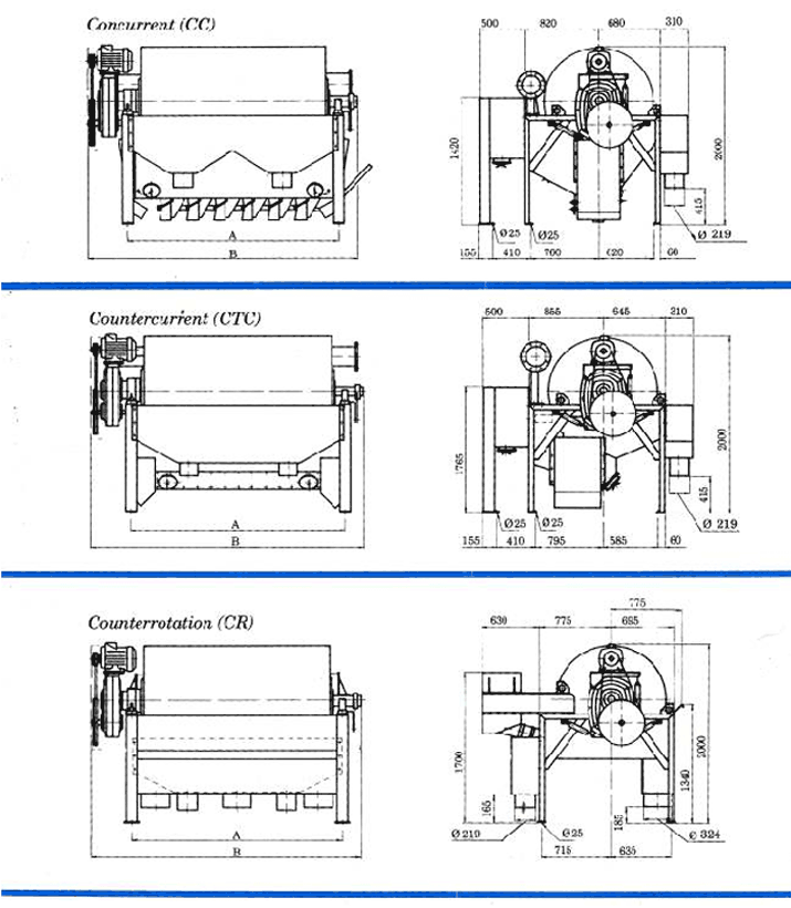
 TANK CONFIGURATIONS




SPECIAL APPLICATIONS

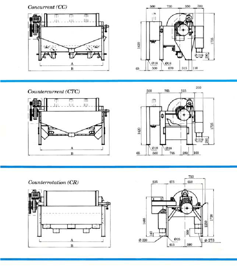


DIAMETER 1200 MM


WET LOW INTENSITY MAGNETIC SEPARATORS
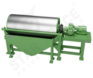
STL is one of the leading manufacturers of ore dressing equipment. The present range of STL process equipment enables us to provide complete packages. Magnetic wet separators constitute an important part of the product range and are known for advanced engineering design and excellent performance.
As a result of continuous development in separator technology STL can offer a complete line of magnetic wet separators to the mining and mineral industries.
PRODUCT MODELS AND SIZES THE STL MAGNETIC SET SEPARATOR DIA. 1200MMSTL's wet permanent magnetic separators are offered in sizes of dia.1200 mm and 916mm in Lengths of up to 3000mm. Three basic separator designs are available for cobbing, roughing and finishing/cleaning applications. Each type can be supplied in single drum or multiple drum stages of taco nite or magnetite and also for recovery for magnetic medium in dense media plants. The stationary magnet yoke is an assembly of strontium-ferrite permanent ceramic magnets. The rotating drum is available with optional rubber or stainless steel covers. The magnetic flux pattern will match the tank configuration for optimum performance.
STL's magnetic wet separator dia 916 x 300 mm is the smallest full scale separator in the 916 series and is primarily used for pilot plant tests. The separator can be delivered in concurrent, counter current and counter rotation versions.
STL's magnetic wet separator for laboratory use have drum dimensions dia. 600 x 285 mm and dia. 200 x 100 mm and are suitable for batch or continuous testing. The test results from the STL laboratory separators correspond closely to those obtained in full scale operation.
STL's magnetic wet separators have been developed in close cooperation with the Swedish mining industry for treatment of magnetite. A prime consideration in its advanced engineering design has been high capacity, improved metallurgical performance and highest availability. The separator is constructed as a separate unit consisting of drum with magnet yoke, tank and drive package, all mounted on a heavy-duty frame. The design of the frame allows any number of units to be connected in series as multi-stage installation. This design offers a flexible flow sheet layout.
ADJUSTMENT OF MAGNET YOKE AND DRUM
The magnet yoke is mounted on the stationary drum shaft and its position can be adjusted (+/-35 °) by a lever at the end of the drum shaft to optimize running conditions in accordance with tank design and type of ore. The gap between tank and drum, which determines the pulp flow speed, can be adjusted vertically by shims inserted under the bearing housing and shaft support. Horizontal adjustment is by slotted holes.
DRIVE UNIT
The standard drive train consists of a shaft end mounted torque arm speed reducer outside the tank with V-belt pulley driven from a standard electric motor. This arrangement provides a smooth protected transmission and has several advantages compared to chain drives. Also other drive arrangements can be supplied.
The V-belt drive is protected by a steel guard. As an alternative the separator drive unit can be supplied with an easily removable fiberglass cover. These covers protect the entire drive unit and motor, with opening for lubrication maintenance and inspections.
The Steel V-belt guard is preferred for users in extreme climatic conditions, e.g. tropical and subtropical.
FEED AND DISCHARGE BOX
The feed box is designed for high capacities with a uniform distribution of pulp over the full length of the drum. Removable tramp screens can be provided as an option.
The discharge box is bolted to the heavy-duty frame and designed to give a smooth and easy discharge of the concentrate. Wear surfaces are typically rubber-lined.
IRON RECOVERY

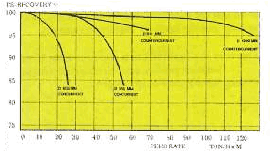
A series of investigations have been made to study the effect of magnetic field strength on feed rate and iron recovery.
It is evident from the results shown on the diagram to the left how the capacity and recovery figures increase at higher field strength. The studies were made on dia.916mm separator fed with a magnetite ore ground to 75% minus 0.044mm (325 mesh) and separated at 30% solids by weight.
The diagram to the right shows the importance of correct tank design with respect to particle size.
As shown increased magnetic field strength gives decreased relative iron losses in the tails for finer fractions. It also proves that the counter current tank configuration produces a better recovery than the concurrent type in the fine particle range at the same magnetic field strength. For coarser fractions the concurrent type is superior.The feed box is designed for high capacities with a uniform distribution of pulp over the full length of the drum. Removable tramp screens can be provided as an option.
INFLUENCE OF DIFFERENT DRUM DIAMETERS

Above Figures are based on a test run and should not be used for dimensioning.
For many years drum diameters 600mm, 760 mm and later on 916 mm dominated the sales of wet low intensity magnetic separators.
Realized the advantages of the larger drum diameter and was first to introduce the 1200mm diameter drum. The results from actual operations confirm the vast improvements in performance and capacity with 1200mm drums.
The feed to the separators consisted of partially martitised magnetite ore ground to 75% minus 0.044mm (325 mesh) and the purpose was to produce a concentrate containing less than 1% SiO2.
A comparative study was also made using different drum diameters but with the same magnetic field strength rating 850 Gauss. The curves shown(right) are a summary of this study. Another advantage worth noting with increased drum diameter is higher concentrate densities and grade.

In the concurrent separator the product enters the feed box from which it is uniformly distributed over the full length of the drum. The pulp passes over a weir in the tank which directs flow against the drum, where upon the magnetic particles immediately are attracted to the drum. The concentrate is carried forward by the drum and passes through a gap where it is dewatering before leaving the separator. The tailing s are discharged through adjustable bottom valves. For best separation results feed pulp density should be 35- 45% by weight solids.

The pulp level must be kept constant and approximately 25mm above the lower edge of the drum. This level is adjusted with the bottom valves and is reached when pulp overflows the tank side weirs. The standard STL concurrent separators is capable of handling material with particle sizes up to 6mm Special tanks can be supplied for coarser material.
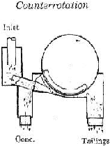
The operation of the counter current separator differs from that concurrent type in that the tailing s are forced to travel in the opposite direction to the rotation of the drum.

Extra water can be added through specially designed jet pipes, by which sedimentation of coarser particles is avoided.

The STL counter current separator can handle fluctuating flows within wide limits. Best operating results are obtained at about 30% solids by weight. This type of separator can handle particle size up to 0.8mm (20 mesh). Adjustment of pulp level is not required.
The counter rotating separator is recommended for applications where recovery is more important than grade. The pulp flows in opposite direction to the drum rotation and the extended magnet angle provides an extra long pick-up zone for maximum recovery.
The particle size handled can be up to 3-4mm (5mesh). The best operating performance is obtained with pulp containing 30 - 40% solids by weight.

A special type of separator is available for dense media recovery, requiring ability to treat dilute pulps with low content of very fine magnetic particle at extremely high recoveries. The dense media recovery separator has a modified tank of concurrent type with an extra long pick-up zone. A specially deigned high gradient assembly is recommended for treatment of very dilute media.
MAGNETIC FIELD STRENGTH


The magnetic systems consist of ceramic strontium ferrite magnets and are designed to produce highest flux, gradient and flux patterns to match each tank configuration.
The magnet systems have the highest field strength in the pick - up zone, and gradually decreasing strength in the transport and dewatering zones.
Above are shown typical field strength charts for STL magnetic wet separators dia. 1200mm.
APPLICATIONS OF WET LOW INTENSITY MAGNETIC SEPARATORS
The capacity varies considerably depending on metallurgical criteria. Most important variables are magnetic susceptibility characteristics of the magnetic particles, degree of liberation and size of the feed.
Mechanical features of the separator as tank design, magnet system and drum diameter do of course also effect the capacity. The following capacity figures can be used as guide-lines for STL magnetic wet separators in iron ore processing.

Above Figures applicable for iron ore processing.
As summary of the field experience and confirmed by test runs, following advantages can be emphasized when using the dia. 1200Mm separators specially for new projects:
- Reducing the total number of separators required.
- Lower operation and maintenance costs.
- Less number of pumps, pulp distributors, etc
- Less occupied floor space.
- Lower building cost.
SPECIAL APPLICATIONS


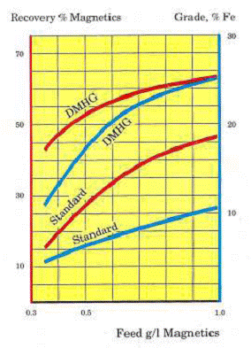
For applications involving fine or very fine particles, low content of magnetic material, and/or where highest recovery is desired, the HG- type magnetic assembly has been found to be superior to the standard assembly. The diagram to the right is an example on recovery of magnetite from floatation tailing s in true comparison with standard magnetic assembly.
The DMHG unit is designed to give a higher gradient than the standard assembly. The magnetic field strength is, however, lower. Thus the capacity measured as t/h x m drum length is down rated to correspond to the lower field rating.
The natural place for this separator is e.g. On a tailing s stream from a magnetite plant, secondary separator in a dense media recovery circuit, or recovery of metal powder production.

The above volume capacities are indicative for optimum performance at average conditions. Higher volumes can be allowed under special conditions.
Specification for Wet Low Intensity Magnetic Separators
DIAMETER 916 MM


DIAMETER 1200 MM


